- Dependency Structure Matrix
- Analyze dependency matrix
- Explore dependencies
- Find usages for dependencies
- Limit the DSM scope
- DSM tool window
- Cycles
- Module dependency diagrams
- View module dependencies diagram
- Analyze module diagrams
- Manage module dependencies diagram
- Dependency Diagram
- Show Diagrams
- Zoom in
- Finding a specific dependency
- Focus on related nodes
- Select scopes
- Module Dependency Diagrams
- Building a module dependency diagram
- Analyzing a module dependency diagram
- Navigating from the diagram to the source code
Dependency Structure Matrix
The bundled Dependency Structure Matrix plugin must be enabled.
Working on complicated projects with numerous dependencies makes it difficult to understand where to look for problems. You might encounter complex relationships, or cyclic dependencies, that may seriously affect application performance and behavior. This is where DSM helps.
DSM stands for Dependency Structure Matrix – a method that helps you visualize dependencies between the parts of your project (modules, classes, and so on) and highlight the information flow.
DSM analysis can be used to see how changes will affect the project. For example, if one of the classes needs to be changed, you can identify all dependencies and see how this change will propagate through the project.
Analyze dependency matrix
- From the main menu, select Code | Analyze Code | Dependency Matrix . Alternatively, right-click an item in the Project tool window and select Analyze Dependency Matrix .
- In the dialog that opens, select the scope that you want to analyze, and click Analyze .
If your project class files are out of date, the analysis may result in incomplete or incorrect data. To avoid this, IntelliJ IDEA prompts you to compile a project before continuing the DSM analysis.
The DSM tool window will open enabling you to examine dependencies. By clicking the cells in the tool window you can go in more detail.

DSM tool window sorts dependencies in a special way: classes, which are used most are moved to the bottom.
On the matrix, all dependencies always flow from green to yellow: when you select a row, green annotations show dependent components, while the yellow ones show components on which the selected components depend. Mutual dependencies are shown in red. Various shades correspond to the number of dependencies. The more dependencies there are, the darker the corresponding cell is.
Explore dependencies
You can limit the view to see only selected dependencies. In contrary to the Limit Scope option, only classes which produce selected dependencies are left.
- In the DSM tool window, right-click the necessary dependency and select Explore Dependencies Between . The classes that produce these dependencies will be opened in a new tab in the DSM tool window.
Find usages for dependencies
You can open selected dependencies for further source-code analysis.
- In the DSM tool window, right-click the necessary dependency and select Find Usages for Dependencies .
Limit the DSM scope
You can limit the scope of your DSM to the selected rows. Only these will remain in the new matrix.
- Select the rows you want to keep, and from the context menu, select Limit Scope To Selection . The limited scope will be opened on a new tab in the DSM tool window.
DSM tool window
This tool window becomes available after performing DSM analysis.
Here you can see the typical matrix view.

The row headers represent program structure. Everything is collapsed now and only modules are shown. When expanded, the header is tree-like, allowing you to expand modules and dig into program packages. * — node groups classes inside the package. The column headers are the same as the corresponding row headers. Thus, they are not shown in order to save space. Instead, different visual aids are used on the row headers.
If you select a row, the matrix will look like this.

Here you can learn the following:

- The selected row and corresponding column are highlighted to visualize row dependencies.
- The ellipsis in the cell means that the maven-core module has many (more than 99) dependencies on maven-project module.
- The column shows the dependencies of the selected row.
- The row shows the dependencies on the selected row.
- This means that the maven-project module has 16 dependencies on maven-settings module.
- Various shades correspond to the number of dependencies.
- Color annotations help to visualize row dependencies at a glance.
- maven-core depends on maven-project .
- maven-project depends on maven-profile .
- The dashes on the diagonal correspond to self dependencies which are not shown.
You can select any cell to explore the dependencies indicated in it.

The cell #1 was selected. These color annotations mean that maven-project has 16 dependencies on maven-settings . The symmetrical cell (cell #2) shows dependencies in the other direction — in this case zero.
There is a simple mnemonic rule — all dependencies always flow from Green to Yellow.
Instead of alphabetically sorting rows, DSM view sorts dependencies in a special way: classes, which are used most are moved to the bottom. In a project with good structure this creates a triangular shape in the lower left half of the matrix.
Cycles

Mutual dependencies are shown in red. It means that the plugin and usability packages are both dependent on each other.
Источник
Module dependency diagrams
When you work with a large multi-module project, sometimes it is more convenient to check how modules and their dependencies are connected in a graph.
You can view, analyze, and manage UML diagrams for the following modules:
- Project modules — which are part of your multi-module project.
- Java modules — which are part of the Jigsaw project that comes with JDK 9. To view and manage such diagrams, make sure you have the JDK 9 or a later version installed.
To view the documentation on Spring, Maven, or Gradle diagrams, refer to the appropriate sections for Spring, Maven, and Gradle.
View module dependencies diagram
- From the main menu, select View | Tool Windows | Project ( Alt+1 ), select an item (project/module) for which you want to view a diagram.
- Right-click the selected item and from the context menu, select Diagram | Show Diagram (or press Command Alt Shift U ).
- From the list that opens, select a type of the diagram you want to create.
IntelliJ IDEA displays a module and its dependencies.
When you work with Java modules, keep the following in mind:
- IntelliJ IDEA allows only one Java module per one IntelliJ IDEA module.
- You can create a diagram for the JDK module as well. For example, right-click the java.jnlp file and from the context menu select Java Modules Diagram .
- You can open the module-info.java file in the editor and from the context menu also create a diagram.
Analyze module diagrams
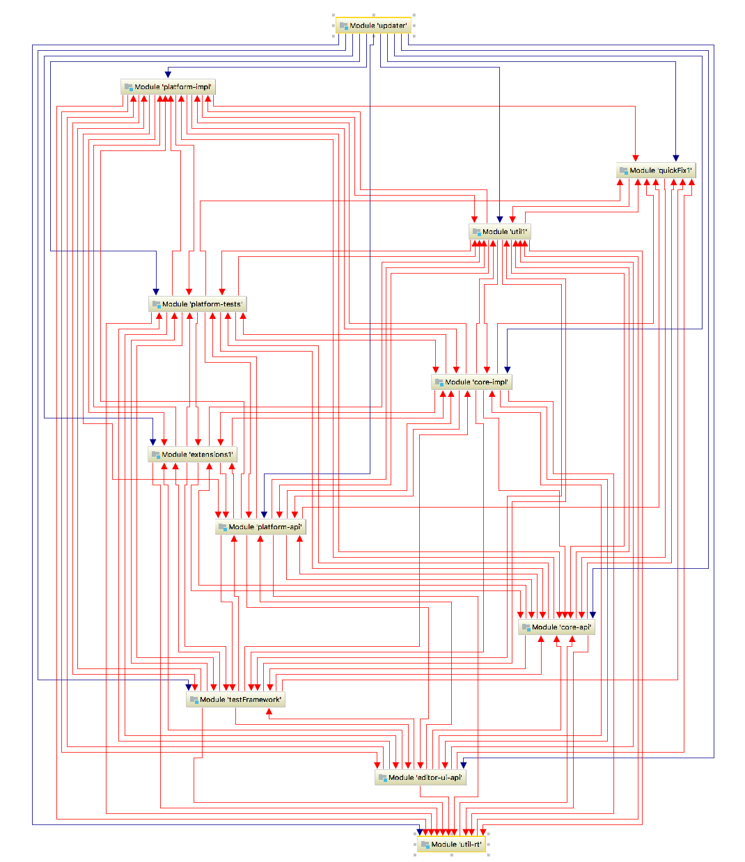
After you have generated a module dependencies diagram you can analyze modules and their dependencies.
For Project modules , UML conventions are followed when IntelliJ IDEA displays connections (arrows) between module dependencies. However, IntelliJ IDEA uses the following colors to display certain connections between modules and dependencies:
- blue arrows are reserved for libraries and modules dependencies
- green — for test dependencies
- red — for circular dependencies
In projects with Java modules , you can easily spot named or automatic modules since IntelliJ IDEA displays them in different colors:
- brown is reserved for IntelliJ IDEA modules
- yellow is reserved for named modules (contain module-info.java )
- blue is reserved for automatic modules
IntelliJ IDEA displays connections between modules and transitive dependencies with bold arrows. In this case, you can always see what gets pulled in with the module.
Manage module dependencies diagram
IntelliJ IDEA lets you manage your diagram performing basic diagram actions such as jumping to the source code, finding usages, and so on.
Check the following useful actions:

- If you have a large graph with lots of modules and connections — use Alt+mouse to zoom in on different parts of your diagram.
- You can jump to the source code — select the desired item and press F4
- You can quickly locate a module or a library if you have too many items in your graph — press Control+F and from the list that opens, select the element you’re looking for.
- You can view usages of the diagram element in the project files — select the desired element and press Control+Alt+F7 .
Источник
Dependency Diagram
If you are using IntelliJ IDEA Ultimate, you can also view your dependencies as a diagram.
Show Diagrams
We can open diagrams either by right-clicking the project in the Project tool window and selecting Diagrams | Show Diagrams, or by using the shortcut ⌥ ⇧ ⌘ U (on macOS) or Ctrl+Alt+Shift+U (on Windows/Linux). You’ll notice this gives you several diagram options to choose from. In this case, we’re interested in the Gradle Dependencies, so we select that one. We can hide all tool windows (⇧⌘F12 on macOS / Control+Shift+F12 on Windows/Linux), so we can focus on the diagram.


Zoom in
If the project we’re looking at pulls in a lot of transitive dependencies, like this example, the diagram can be quite large. We can zoom in and out using the + and — keys, or the + and — buttons in the diagram window.


Finding a specific dependency
To look for a specific dependency and see where we get it from, we can search for this dependency using ⌘F(on macOS) or Ctrl+F (on Windows/Linux) to find it in the diagram. Using the button Show Paths: Root -> Selection, we can check the path for this dependency and click related dependencies to follow the path to the root.


Focus on related nodes
We have other options to look into specific dependencies. For example, we can zoom in on a specific dependency and the related nodes. Right-click the dependency you’re interested in, and from the context menu, select Analyze graph > Focus on Node Neighbourhood. This will give you several options. In this example, we’ll look at both directions. When we are done, we can reopen Analyze graph context menu and select Drop focus.


Select scopes
We can change the visibility level, by clicking the Change Visibility Level button for example if we want to focus on compile or runtime dependencies only.
Источник
Module Dependency Diagrams
With IntelliJ IDEA, you can get visualization of imports and exports within a context in JavaScript and TypeScript projects.
Building a module dependency diagram
- Choose Diagrams | Show Diagram from the context menu of a JavaScript, TypeScript, or HTML file or on a context menu of a folder. The action is not available for node_modules and for Excluded folders.
- If the action is invoked on a folder where multiple types of diagrams can be built, additionally choose JavaScript Module Dependency Diagram from the Select Diagram Type list.
Analyzing a module dependency diagram
IntelliJ IDEA analyzes the import and require statements and script tags in the selected file or in all the files in the selected folder recursively and in a separate tab displays a diagram that shows how these files depend on each other:
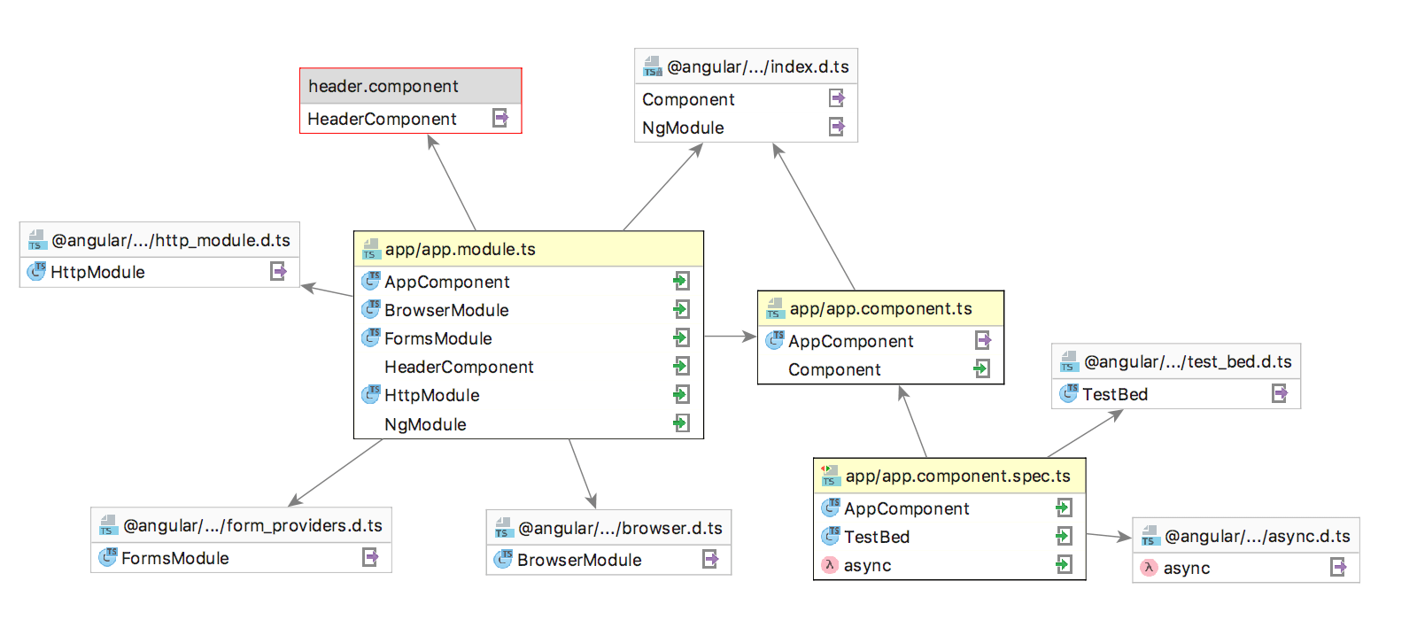
- A diagram consists of a number of rectangles. Each of them shows the name of the analyzed selected file and a list of detected imports. If an import is resolved, an icon that indicates the type of the imported symbol (e.g. or ) is shown next to it.
- An arrow from an analyzed file points at the target file from which the detected imports are made. If the target file is a library, its name is displayed on the grey background. If an import from a library is not resolved, the target file is displayed as a grey rectangle with red border.
- Resolved imports and exports are marked with the or icons respectively.
Navigating from the diagram to the source code

- To jump from a diagram to a file, right-click the file and choose Jump to source on the context menu.
- To navigate to a specific import statement in the source code, right-click the required file in the diagram, choose Jump to on the context menu, and then choose the symbol to jump to from the Select Navigation Target list:
Источник